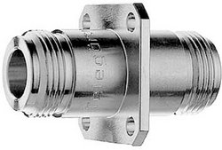
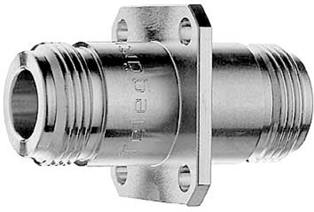
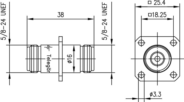
N Panel Adaptor with flange f-f
N Panel Adaptor with flange f-f
Technical attributes
| Article name | N Adapt str Flng f-f |
|---|---|
| Type | f-f |
| Return Loss | typ.: 1 GHz: -41 dB; 4 GHz: -35 dB; 11 GHz: -27 dB |
| MIL-Std. | UG-129/U |
| Mount. dim. | Z008 |
Downloads
Description of the Series/Product Category
Notice: The following information refer to the series/product category as a whole. Please see the specific datasheet for specific technical information of a particular product.
The N series is a very popular coax connector. It is a medium sized, precision, weatherproof connector supplied with a screw coupling. In some applications this connector can be used up to 11 GHz. Only 50 Ω impedances are available. Connector styles are available for flexible, conformable, semi-rigid and corrugated cable types. Both crimp and clamp cable termination processes are used for this series. Special design techniques for this series of connectors have resulted in excellent levels of performance with regard go return loss (VSWR) and intermodulation distortion. Applications for these connectors vary from signal and data transmission where vibration resistance and environmental protection is required. N series provides a medium-power high-frequency solution for coax connections.
Mating face sealing for N connectors between plug and jack (mated) according to IP 68. The classifications are general statements for the relevant series. Individual connectors may deviate from the values shown. If in doubt, please consult our engineers.
Mechanical attributes
| Recommended coupling torque | 4 - 6 Nm |
|---|---|
| Durability (Matings) | ≥ 500 |
| Material: spring contacts | CuBe2, CuNi1Pb1P(C97) |
| Material: outer conductor | CuZn39Pb3 |
| Material: other metal parts | CuZn39Pb3 |
| Material: insulators | PTFE |
| Material: gaskets | Silicone, NBR |
| Finish: Inner conductor | Cu2Ag5 |
| Finish: Outer conductor | CuSnZn3 (Telealloy); Ag2CuSnZn0.5 (Optargen) |
| Finish: Other metal parts | CuSnZn3 (Telealloy), Cu2Ni5 |
Thermal and climatic attributes
| Climatic category acc. to IEC 60068 - 1 | 55/155/21 |
|---|
Elecrical attributes
| Contact resistance inner conductor | ≤ 1,5 mΩ |
|---|---|
| Contact resistance outer conductor | ≤ 1 mΩ |
| Insulation resistance | ≥ 5 GΩ |
| Voltage proof | 2.5 kVeff/50 Hz |
| Impedance | 50 Ω |
| Return loss: Straight style | ≥ 30.5 dB/1 GHz |
| Return loss: Angle style | ≥ 30.5 dB / 1 GHz |
| Working voltage | ≤ 1 kVeff/50 Hz |
| Frequency range up to | 11 GHz |
Norms
| Standards | IEC 61 169-16 |
|---|
Note :
Combination connectors and cable clamps can be utilised to create a further number of N connector variations.
RF cable assemblies with N connectors upon request.


