


- Knowledge-Center
- Copper Networks

Find information about:
- Standards
- Cabling models: Permanent Link and Channel / Links with 2, 3, 4 Connectors / Consolidation Point
- Class, Category, Cable types
- Connecting Hardware
The most important standards at a glance
DIN EN 50173
EN 50173 has become a series of six standards, focusing on different environments and scenarios:
- DIN EN 50173-1:2018 General requirements
- DIN EN 50173-2:2018 Office spaces
- DIN EN 50173-3:2018 Industrial spaces
- DIN EN 50173-4:2018 Homes
- DIN EN 50173-5:2018 Data centre spaces
- DIN EN 50173-6:2018 Distributed building services
ISO/IEC 11801
ISO/IEC 11801 is the international set of standards for structured cabling. It is very similar to EN 50173, and since November 2017 it even has the same structure of six parts:
- ISO/IEC 11801-1:2017: General requirements
- ISO/IEC 11801-2:2017: Office premises
- ISO/IEC 11801-3:2017: Industrial premises
- ISO/IEC 11801-4:2017: Single-tenant homes
- ISO/IEC 11801-5:2017: Data centres
- ISO/IEC 11801-6:2017: Distributed building services
TIA-568
Apart from ISO / IEC 11801, the American standard TIA-568 is very common in the United States. Currently, the fifth issue of TIA-568 is published as TIA-568-D, which replaces all preceding ones.
The set of TIA-568-D consists of five parts:
- TIA-568.0-D: Generic Telecommunications Cabling for Customer Premises
- TIA-568.1-D: Commercial Building Telecommunications Infrastructure Standard
- TIA-568.2-D: Balanced Twisted-Pair Telecommunications Cabling and Components Standard
- TIA-568.3-D: Optical Fiber Cabling and Components Standard
- TIA-568.4-D: Broadband and Coaxial Cabling and Components Standard
Some specifications of TIA-568-D differ from the ones in ISO / IEC 11801 and thus EN 50173. TIA-568 applies only to the U.S.A. unless explicitly stated otherwise.
Cabling models
Permanent Link and Channel
The permanent link comprises the components that will stay permanently in place, so in most installations this means patch panel, horizontal cable, and outlet.
„Channel“ means the whole connection between two electronic devices like a PC and a switch, including all necessary patch cords (very often, the channel consists of the permanent link and the patch cords). In most cases, the channel will only be tested when problems have occured to make sure that the whole cabling is fine. After the installation is done, nearly always the permanent link is tested. The reason for this is simple: Following the test procedures for the channel would mean that all of the patch cords had to remain plugged into the outlets and patch panels.
Permanent Link and Channel

Links with 2, 3 and 4 Connectors
A link can contain two to four connections. The connections directly at the electronics like switches or at the equipment like PCs are not taken into consideration.
Permanent link and channel contain in the most simple configuration just one connection at the patch panel and one at the information outlet. Link and channel can also have a consolidation point near the outlets, which is common in large office spaces. There can be one more connection in the distributor, e.g. when the active components like switches are connected to a patch panel of their own. Patch cords connect the patch panels of the switch and the horizontal cabling, which is called a „cross-connect“. Cross-connects are popular in the United States but are rarely used in Europe.
Channel with 4 connectors

Cabling with Consolidation Point
Sometimes it is useful to lay a bundle of horizontal cables between the floor distributor and a consolidation point, which is made of a group of outlets or a small distributor. From the consolidation point, cables are run to fixed or mobile outlets, to which PCs or other end devices are connected. An example of a consolidation point is a small distributor, installed in suspended ceilings or cellular floors in open-plan offices or for industry solutions, where cover plates or utility columns provide flexibility. Floor outlets may also serve as consolidation points when patch cords plugged in, which are not connected to PCs but to other outlets in desks or furniture.
Class and Category
„Class“ means something completely different than „category“. The class (or „category link“ according to TIA) always applies to the installed link, the category as such applies only to one single component, e.g. the cable or the outlet; the component is tested and verified by either the labs of the manufacturer or independent verification labs. The installed link is always tested according to classes (or category links).
Cabling classes acc. to ISO/IEC:
Class D: up to 100 MHz, for data rates up to 1 Gbps
Class E: up to 250 MHz, for data rates up to 1 Gbps
Class EA: up to 500 MHz, for data rates up to 10 Gbps
Class F: up to 600 MHz, for muti media applications
Class FA: up to 1.000 MHz, for multi media applications
Class I: up to 2.000 MHz, for data rates up to 40 Gbps
Class II: up to 2.000 MHz, for data rates up to 40 Gbps
Component categories acc. to ISO/IEC:
Category 5: up to 100 MHz, for data rates up to 1 Gbps
Category 6: up to 250 MHz, for data rates up to 1 Gbps
Category 6A: up to 500 MHz, for data rates up to 10 Gbps
Category 7: up to 600 MHz, for multi media applications
Category 7A: up to 1.000 MHz, for multi media applications
Category 8.1: up to 2.000 MHz, for data rates up to 40 Gbps
Category 8.2: up to 2.000 MHz, for data rates up to 40 Gbps
Class I/II and category 8.1/8.2: Class I and class II channels are specified for a maximum length of 30 m. 24 m of them are for the horizontal cable (permanent link) and 3 m patch cords on each end. Category 8.1 is based on category 6A. It recognizes the RJ45 connector of IEC 60603-7-81 and is backwards compatible to categories 5, 6 and 6A. Category 8.2 is based on category 7A. It is backwards compatible to all all other categories including 7 and 7A, but specifies a plug that is not compatible to RJ45 jacks, e.g. the TERA connector of IEC 61076-3-104 or GG45 or ARJ45 of IEC 60603-7-82. IEEE specified 40 Gigabit Ethernet 40GBASE-T with an RJ45 compatible plug, so category 8.2 components are very rarely used.
After 40GBASE-T was standardized, IEEE added 25GBASE-T. Its data rate is 25 Gbps, which is a little more than half of 40GBASE-T. 25GBASE-T runs over cabling components that meet the specs of Cat.8.1 only up to 1250 MHz. In other words: When users want to specify or use Cat.8.1 components, they have to make sure that these components meet the specs of EN 50173-1 within the full frequency range of up to 2000 MHz; if they meet the specs only up to 1250 MHz, they can transmit only a bit more than half the data rate.
The correct spelling of Class EA and Category 6A: Originally, an „a“ in lower case was used. Later on, TIA and ISO agreed to use an „A“ in upper case. ISO (and thus Cenelec) use the „A“ in subscript (A), TIA uses it in the same level as „6“:
- Link and channel according to ISO: Class EA
- Link and channel according to TIA: Category 6A
- Components according to ISO: Kategorie 6A
- Components according to TIA: Category 6A
Cabling Systems vs. Mix & Match
Even though the cabling standards were created to offer the possibility of using components from different vendors in the same link, standard compliant links („mix & match“) might lead to serious problems. The specifications allow large tolerances and different vendors may use different ways of eliminating capacitive and inductive interference. It may well happen that components of standard compliant systems cause reflections of the signal, which lead to high bit error rates. The system becomes slow and offers only poor performance.
Cabling systems vs. mix & match

Connecting Hardware
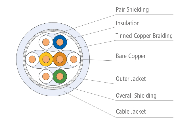
Twisted Pair Cables
ISO developed a standardized, systematic naming for the different types of construction of twisted pair cables. The first letter stands for the overall screen, the second one – separated by a slash – stands for the element screen. „S“ means braid screen, „F“ means foil screen. „TP“ stand for twisted pair, the balanced element..
Different types of twisted pair cables:
- S/FTP: overall braid screen (S), elements foil screened (FTP)
- F/TUP: overall foil screen (F), elements unscreened (UTP)
- SF/UTP: overall braid and foil screen (SF), elements unscreened (UTP)
- U/UTP: no overall screen (U), elements unscreened (UTP)
Twisted pair cables are available with solid and stranded conductors.

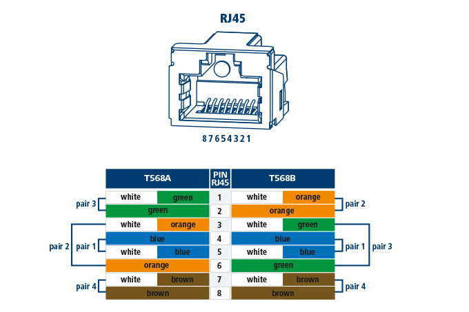
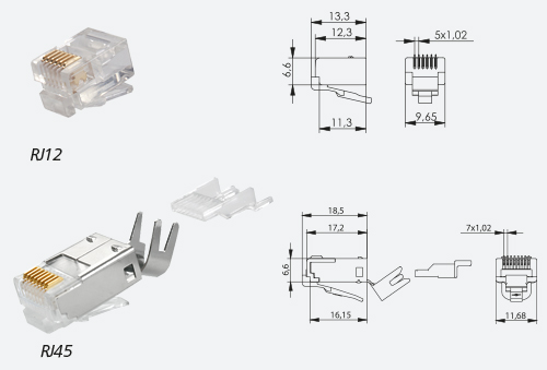
RJ45 Connectors
The RJ45 has become the dominant connector for copper cabling. The term “RJ45” is not standardized, but it’s widely used. The American term 8P8C is more precise. „P“ stands for „positions“ and „C“ for „contacts“. An 8P8C connector has 8 positions for the contacts and 8 of them are populated. The standard series EN 60603-7 (international: IEC 60603-7) specifies the RJ45 in both, shielded and unshielded versions, and from category 5 to category 8.1.
The American standard TIA-568 defines two different colour codings for RJ45 plugs and jacks. The colour coding T568A was originally developed for the military and is still mandatory for U.S. federal installations.
Circular Connectors
In industrial and transport applications circular M12 and M8 connectors are used. Their metric threading ensures reliable connection even during vibrations.
The D-coded M12 accepts four wires, meets the category 5 specifications and thus can be used for data rates up to 100 Mbps.
The X-coded M12 has the same size as the D-coded version but accepts four wire pairs, which are completely separated from each other by a metal shielding cross. The M12-X meets the category 6A specifications and can be used for data rates up to 10 Gbps.
The M8 accepts four wires like the M12-D, meets the category 5 specifications and thus can be used for data rates up to 100 Mbps. It is much smaller than the M12 and is an ideal solution for applications in restricted spaces.

Outlets with boards or individual modules
Constantly growing technical requirements and at the same time cost pressure demanding shorter installation time were successfully solved by the modular design of the connecting hardware. In the old days, outlets contained small printed circuit boards to which the jacks were soldered.
Now the jacks are mounted directly on the end of the cable and just snapped into the frame of the outlet or the patch panels. Each cable is terminated on both ends with an individual jack. This leads to a much better electrical performance of the link and to an enormous time saving when terminating the cables and installing the connecting hardware. An additional benefit: Individual links can be added later at much lower costs. Either concept works, and Telegärtner offers both of them, of course. The AMJ K Cat.6A was the first board based outlet with LSA+ contacts and Cat.6A performance verified by the independent test lab GHMT worldwide.
Horizontal cables do not necessarily have to be terminated with a jack. When they are terminated with a plug, they can be inserted into an outdoor housing of an IP surveillance ca- mera, for example. There is no need anymore for an outlet near the camera. This benefit is also welcome by industrial applications, and even in residential cabling the outlet can be omitted – in many installations there is no space for an outlet anyway. Good plugs can be mounted on site and can be used for any application, from analogue telephony up to 40 Gigabit Ethernet.
Power over Ethernet (PoE)
With PoE, the devices can be powered using the data cable. The standards body IEEE has specified PoE in the industry standard IEEE 802.3 and its amendments:
PoE and especially PoE+ and 4PPoE demand high quality connecting hardware as the small contacts have to transmit data and power at the same time. The contact design plays a key role with Power over Ethernet. When an RJ45 plug is unplugged while the end device is still powered over the data cable, sparcs occur that will damage the small contacts of plug and jack. The sparcs cannot be avoided, so it is vitally important that the area where data is transmitted is far away from the area where the sparcs damage the contacts. With such a PoE optimized design, the connection can transmit the full data rate even after multiple disconnections under load.
Versions of Power over Ethernet:
| Standard | Year | Power at the device typ. | Electrical current per wire pair | |
| PoE | IEEE 802.3af | 2003 | 12,95 W | 350 mA |
| PoE+ | IEEE 802.3at | 2009 | 25,5 W | 600 mA |
| 4PPoE | IEEE 802.3bt | 2019 | 51,0 W 71,3 W | 600 mA 960 mA |
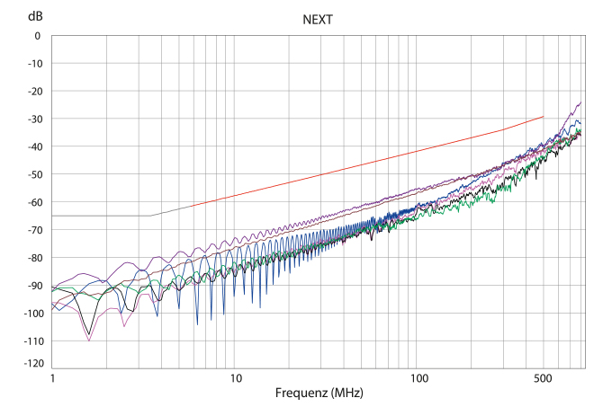
De-embedded / Re-embedded
The cabling infrastructure of high speed data networks calls for high tech testing, especially when testing individual components. The de-embedded testing method was developed for Cat.6 components. It uses a reference jack which has to be tested with 12 different plugs to ensure it can cope with the complete spectrum of mix & match applications.
Of course, this leads to different margins with the different connectors, and all of them have to be standard compliant. De-embedded testing is precise enough for testing individual components of category 6 up to 250 MHz for data rates up to 1 Gbps. Despite of this effort, this testing method is not precise enough for testing Cat.6A components up to 500 MHz for data rates up to 10 Gbps. With de-embedded testing, a jack under test was tested as a single, stand-alone item. Re-embedded testing test the jack re-embedded into the board, it tests “the whole thing“. Reembedded testing uses a reference plug with well-known margins. It also uses two test heads, which are connected to a network analyzer. One of this heads has a soldered receptacle for the reference plug; the jack to be tested is connected to the other test head using twisted pairs. Then the two test heads are connected and tested.
Re-embedded testing using multiple boards according to IEC 60512 is still not precise enough for Telegärtner: In the Telegärtner’s test lab, the board with the reference jack is directly connected to the network analyzer using coaxial cables. This has the benefit of eliminating near-end crosstalk (NEXT) and effects caused by interference among the twi- sted pairs. The special testing procedure with coaxial cable enables higher precision than the procedure according to IEC 60512.
Telegärtner Real-Time Re-Embedded Cat.6A
Using an 8-port network analyzer with implemented re-embedding calculation, the Real-Time Re-Embedded test procedure by Telegärtner makes real-time evaluation of connecting hardware possible. With this, effects of any changes of the device under test can be tracked in realtime. The time consuming testing of all pair combinations belongs to the past.
Cat.6A Patch Cords
In many installaitons, patch cords are ignored – with unpleasant consequences, as the cabling infrastructure will not reach it’s full performance when low-cost patch cords degrade the quality of the channel. But how can one tell that a specific path cord is a high quality product? Cat.6A components have been tested using the re-embedded test procedure for quite a while by now, but patch cords haven’t – the physics made it next to impossible.
Once again, Telegärtner lead the way: The Telegärtner test lab was the fist test lab worldwide that was able to test Cat.6A patch cords. The test procedure is more advanced and more precise than specified by international standards.
Telegärtner uses Real-Time Re-Embedded testing, which tests all four pairs simultaneously with an 8-port network analyzer. This high-end test procedure without baluns leads to much more precise test results and sets the trend for testing high-quality patch cords. This ensures that the channel can transmit the full data rate.