


- Knowledge-Center
- Basic Knowledge Fiber Optic Networks

Design of Optical Fiber
State of the art fiber optic cables contain multimode fibers with graded refraction index (marked with a „G“) or singlemode fiber (marked with an „E“). Loosely, one can assume that several rays of light (modes) travel along a multimode fiber in different ways, whereas in singlemode fibers only one of them does so (these „rays“ stand for the main distribution of electromagnetic energy that satisfies Maxwell’s equations and boundary conditions in guided wave propagation).
Singlemode and Multimode
The light is guided in the inner part of the fiber. The outer part ensures that only light that doesn’t exceed a certain angle can enter the fiber, that it will be guided travelling along the fiber, and that light which left the inner part may not reenter causing signal irritation. The inner part of a fiber is called core (multimode fibers) or mode field (singlemode fibers), the outer part is called cladding. As core and cladding are made of glass with different refraction indices, light will be reflected at the border (total reflection).
Thus, a maximum of light will be guided through the fiber core. Nowadays, multimode fibers with a core diameter of 50 μm are common, in the old days it was 62.5 μm. The two multimode fiber types may not be mixed in the same link, for that would lead to a heavy loss of light, especially when light travels from the 62.5 into the 50 μm fiber. The core diameter of singlemode fibers is typically 9 to 10 μm, depending on the fiber manufacturer and on the wavelength of the light. The outer diameter of all of the fiber types mentioned above is 125 μm.


Types of Optical Fibers
ISO/IEC 11801 and EN 50173-1:2003 specify different performance categories for optical fibers. There are five of them for multimode fibers (OM1 to OM5) and two for singlemode (OS1a and OS2, with OS1 fibers being superseded by OS2 by now). Fiber category OS1 of EN 50173 was renamed to OS1a and has now the same designation as in ISO/IEC 11801-1:2017. The specifications of OS1 according to EN 50173 were not changed.
LEDs usually work fine at transmission rates up to 100 Mbps. Gigabit and 10 Gigabit Ethernet use lasers, as LEDs can’t be switched on and off fast enough. Cost-effective VCSELs (vertical cavity surface emitting lasers) work at 850 nm. For other wavelengths such as 1310 nm or 1550 nm, standard lasers have to be used.
| Maximum attenuation [dB/km] | |||||||
| Multimode OM1, OM2 and OM3 | Multimode OM4 | Singelmode OS2 | |||||
| Wavelength | 850 nm | 1300 nm | 850 nm | 1300 nm | 1310 nm | 1383 nm | 1550 nm |
| Attenuation | 3,5 dB | 1,5 dB | 3,50 dB | 1,5 dB | 0,4 dB | 0,4 dB | 0,4 dB |
Plastic optical fibers
Optical fibers do not necessarily have to be made of glass. They can partially or completely be made of plastic. Polymeric optical fibers, also called plastic optical fibers or POF, are completely made of plastic. Unlike glass fibers, polymeric optical fibers cannot be fusion spliced together, as the plastic would just melt. POFs are connected using connectors or clamps. With sharp knives, POFs can be cut precisely, and there is no need to polish the fiber ends.
Connectors for polymeric optical fibers

Bend-intensive optical fibers
Bend-insensitive optical fibers have a lot of advantages in installations with very tight space. Such fibers can be layed in very narrow turns and still offer the full bandwidth. But not all of them are backwards compatible with common optical fibers. Bend-intensitive singlemode fibers are specified in the ITU-T G.657 standard. Fibers of the G.657.A series are fully compatible with standard singlemode fibers as specified in ITU-T G.652. Fibers of the G.657.B series in most cases aren’t, but they have a smaller minimum bending radius than the ones of the A series. Depending on the manufacturer, bend-insensitive multimode fibers (BIMMF) might be backwards compatible with conventional OM3 and OM4 fibers. A look at the data sheet is highly recommended, an explicit statement of the manuf- acturer will help best.
WDM systems
Low waterpeak fibers are very important for WDM systems. WDM stands for wavelength division multiplexing. Where standard systems send light of only one wavelength along a singlemode fiber, WDM systems send multiple rays of light of different wavelengths simultaneously along one single fiber.
Each channel is assigned to an individual wavelength, and to ensure a constant transmission of all signals, the physical properties of the fiber must be the same for all of the channels, i.e. for all of the appropriate wavelengths. Today, WDM systems can only rarely be found in the LAN environment, but still low waterpeak fibers have to be minded when designing or installing new networks to ensure that the future migration towards WDM will be possible wihout replacing the cables. Telegärtner‘s tip Plastic optical fibers Bend-intensitive optical fibers.
Fiber Optic Connectors
FO Connectors
EN 50173 specifies the LC duplex fiber optic connector for the work area (outlets). In legacy installations where the older SC duplex connector is used, links with SC duplex can still be added. For any other area all other connectors specified by IEC standards are allowed.
Many manufacturers of networking devices have begun to use small form factor (SFF) connectors like the LC duplex as they consume not more space than RJ45 jacks. It has to be minded, though, that a high density of connectors in patch panels or consolidation points might proof to be disadvantageous as far as handling, robustness, and clearness are concerned.
In legacy installations, ST connectors can be found alongside with the SC duplex and the LC duplex.
To achieve best possible optical performance, connectors for singlemode fibers are also available in an angled version. Because of the sloping surface of the tip of the connector, reflected light cannot return into the mode field of the fiber but is reflected away from the connector end.

Telegärtner's Tip
Never look into fiber optic connectors or jacks. VCSELs and standard lasers emit invisible infrared light which can cause serious health hazards.
Never plug connectors with a rectangular end (physical contact connector, PC) and connectors with a sloping surface (angled physical contact connectors, APC) into the same coupling. When using APC connectors make sure that slope of both connectors in one coupling has the same angle.
Standardized colour code
EN 50173-1:2018 only specifies colors for plugs and couplings for single-mode fibers:
Singlemode PC, rectangular connector tip
(PC = physical contact): blue
Singlemode APC, angled connector tip
(APC = angled physical contact): green
However, some colours have become common for the different types of multimode fibers as well.
| Connector / Adaptor | Patch Cord | Pre-assembled Installation Cable | |
| OM1 | beige | orange | orange |
| OM2 | beige | orange | orange |
| OM3 | aqua | aqua | orange |
| OM4 | violett | violet | orange |
| OM5 | lime green | lime green | orange |
| OS2 PC | blue | yellow | yellow |
| OS2 APC | green | yellow | yellow |
Colour scheme: connectors, patch cords, pre-assembled installation cables
Fiber optic cabling with MPO connectors
Pre-terminated cabling components with MPO connectors are becoming more and more popular in fiber optic networks. They can be found in data centres, server rooms, equipment rooms of telecommunication service providers and, increasingly, in office buildings. Pre-terminated components are truly plug-and-play which saves a lot of time during installation. On top of that, MPO cabling offers an easy migration path to 40 and 100 Gigabit Ethernet with multimode fibers which use 8 or 20 fibers respectively.
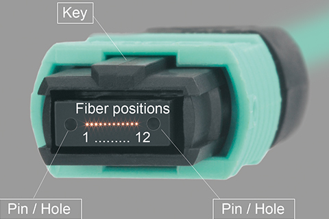
MPO connectors have an alignment key on the top of the connector housing to ensure the connector can‘t be plugged in the wrong way. Two MPO connectors can be plugged together with their keys on opposite sides (key up to key down, known as method A) or on the same side (key up to key up, known as method B). Method C is similar to method A, but the fibers of method C trunks are pairwise flipped to ensure proper fiber polarity in networks where the links have just two fibers.

Telegärtner Tipp
LWL-Verkabelungen sollten unbedingt mit dem Lichtquellentyp gemessen werden, mit dem sie später auch betrieben werden. Die meisten optischen Messgeräte (engl. optical time domain reflectometer, kurz OTDR) verwenden standardmäßig klassische Laser. Für Multimodefasern kommen je nach Netzart jedoch LEDs und VCSELs zum Einsatz, klassische Laser werden für Multimodefasern nur selten verwendet. Die falsche Lichtquelle im Messgerät kann die Messergebnisse verfälschen.